Sometimes you might be frustrated especially when your system detect a wifi network but you are restricted from accessing it due to users password, now i can teach you a simple trick to hack the password.
step one
Go to command prompt, click start up menu on your system, click RUN, type Cmd, and click ok to open the command prompt
step two
inside the command prompt, type the following
netsh wlan show networks
mode = bssid(it will show all the available wifi network, take note of the names)
step 3
To connect to the wifi network, type the following
netsh wlan connect
name= (put the name of wifi your system detect)
e.g net wlan connect
name = (kinibigdeal pc)
step 4
press enter to connect
step 5
To disconnect it, type
netsh wlan disconnect
step 6
To save it type : netsh wlan export profile name = kinibigdeal( not by name but change it to the name of the detected wifi)
How to Hack any wifi Network Password by using Cmd:
Sometimes you might be frustrated especially when your system detect a wifi network but you are restricted from accessing it due to users password, now i can teach you a simple trick to hack the password.
step one
Go to command prompt, click start up menu on your system, click RUN, type Cmd, and click ok to open the command prompt
step two
inside the command prompt, type the following
netsh wlan show networks
mode = bssid(it will show all the available wifi network, take note of the names)
step 3
To connect to the wifi network, type the following
netsh wlan connect
name= (put the name of wifi your system detect)
e.g net wlan connect
name = (kinibigdeal pc)
step 4
press enter to connect
step 5
To disconnect it, type
netsh wlan disconnect
step 6
To save it type : netsh wlan export profile name = kinibigdeal( not by name but change it to the name of the detected wifi)
Thursday, 28 July 2016
What is the difference between RIP, IGRP and EIGRP?
RIP, IGRP and EIGRP are different routing protocols. RIP stands for Routing Information Protocol; IGRP stands for Interior Gateway Routing Protocol; and EIGRP stands for Enhanced IGRP.
The main difference being RIP and IGRP are distance vector protocols; EIGRP is more of link state protocol. Then there is a difference in their operations, times (like updates, refreshes, etc.), how they keep track of routing tables, etc. I talk more about routing protocol's different routing tables in this expert response.
Wednesday, 27 July 2016
Difference Between WCDMA and GSM
WCDMA (Wideband Code Division Multiplexing Access) and GSM are two technologies that are used in mobile telecommunications. The difference between these two is that GSM

The primary reason why telecommunications companies are having problems with rapidly deploying is the difference in the frequency bands they use. Because of this, GSM only phones, cannot communicate with WCDMA only networks and vice versa. In order to circumvent this, it has become common for most phone manufacturers to include multiple frequency bands for both 2G networks and 3G networks. This ensures that their mobile phones can be used in almost any network and any location in the world. Telecommunications companies need to deploy a WCDMA network over their existing GSM network to provide 3G services while still maintaining compatibility with older mobile phones that are not compatible with WCDMA.

Although WCDMA support has become quite common in most mobile phones, there are still some models that do not support it. When you are buying a mobile phone, you should look at its specifications in order to make sure that it supports WCDMA and the frequencies available in your area. This is to ensure that you can use it in your country’s networks. Even non-GSM networks are choosing to add WCDMA support as it is the most popular 3G technology. Sooner or later older and competing network standards, namely GSM, CDMA, and EV-DO, would probably be phased out and replaced with WCDMA.
Summary:
1.WCDMA is a 3G technology while GSM is a 2G technology
2.GSM is slowly being phased out in favor of CDMA
3.GSM is still more widespread than CDMA
4.WCDMA and GSM uses different frequency bands
5.WCDMA offers much faster data speeds than GSM
6.WCDMA would soon replace GSM
1.WCDMA is a 3G technology while GSM is a 2G technology
2.GSM is slowly being phased out in favor of CDMA
3.GSM is still more widespread than CDMA
4.WCDMA and GSM uses different frequency bands
5.WCDMA offers much faster data speeds than GSM
6.WCDMA would soon replace GSM
FDM vs. TDM
FDM vs. TDM
TDM (Time Division Multiplexing) and FDM (Frequency Division Multiplexing) are two methods of multiplexing multiple signals into a single carrier. Multiplexing is the process of combining multiple signals into one, in such a manner that each individual signal can be retrieved at the destination. Since multiple signals are occupying the channel, they need to share the resource in some manner. The primary difference between FDM and TDM is how they divide the channel. FDM divides the channel into two or more frequency ranges that do not overlap, while TDM divides and allocates certain time periods to each channel in an alternating manner. Due to this fact, we can say that for TDM, each signal uses all of the bandwidth some of the time, while for FDM, each signal uses a small portion of the bandwidth all of the time.
TDM provides greater flexibility and efficiency, by dynamically allocating more time periods to the signals that need more of the bandwidth, while reducing the time periods to those signals that do not need it. FDM lacks this type of flexibility, as it cannot dynamically change the width of the allocated frequency.

The advantage of FDM over TDM is in latency. Latency is the time it takes for the data to reach its destination. As TDM allocates time periods, only one channel can transmit at a given time, and some data would often be delayed, though it’s often only in milliseconds. Since channels in FDM can transmit at any time, their latencies would be much lower compared to TDM. FDM is often used in applications where latency is of utmost priority, such as those that require real-time information.
FDM and TDM are often used in tandem, to create even more channels in a given frequency range. The common practice is to divide the channel with FDM, so that you have a dedicated channel with a smaller frequency range. Each of the FDM channels is then occupied by multiple channels that are multiplexed using TDM. This is what telecoms do to allow a huge number of users to use a certain frequency band.
Summary:
1. FDM divides the channel into multiple, but smaller frequency ranges to accommodate more users, while TDM divides a channel by allocating a time period for each channel.
2. TDM provides much better flexibility compared to FDM.
3. FDM proves much better latency compared to TDM.
4. TDM and FDM can be used in tandem.

Sunday, 24 July 2016
IPTV (Internet Protocol television)
IPTV (Internet Protocol television) is the delivery of programming by video stream encoded as a series of IP packets. IPTV is distributed by a service provider and can be free or fee-based and can deliver either live TV or stored video. It can be bundled with other Internet Protocol services, including Voip
and high-speed Internet access.


and high-speed Internet access.


In traditional television delivery, all programming is broadcast simultaneously. The available program signals flow downstream and the viewer selects which program he wants to watch by changing the channel.
IPTV, by contrast, sends only one program at a time. Content remains on the service provider's network and only the program the customer selects is sent to the home. When a viewer changes the channel, a new stream is transmitted from the provider's server directly to the viewer. Like cable TV, IPTV requires a set-top box.

Saturday, 23 July 2016
Friday, 22 July 2016
Difference between hub and switch
Difference between hub and switch
Network Hub

A network hub is designed to connect computers to each other with no real understanding of what it is transferring. Typically, a network hub is used for a private network, one that does not have any connections to sources other than local computers (meaning, no Internet access). When a hub receives a packet of data from a connected device, it broadcasts that data packet to all other connected devices regardless of which one ends up being the final destination. Additionally, network bandwidth is split between all of the connected computers. So, the more computer that are connected, the less bandwidth that is available for each computer, which means slower connection speeds.
Network Switch
A network switch also connects computers to each other, like a hub. Where the switch differs from a hub is in the way it handles packets of data. When a switch receives a packet of data, it determines what computer or device the packet is intended for and sends it to that computer only. It does not broadcast the packet to all computers as a hub does which means bandwidth is not shared and makes the network much more efficient. For this reason alone, switches are usually preferred over a hub.
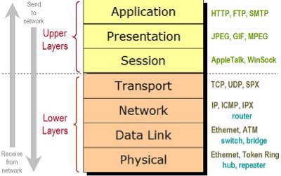
OSI Model layers
The OSI model open system interconnection model defines network to implement protocols in seven layer.

Thursday, 21 July 2016
Router vs Switch vs Hub: The Devices Defined
Router vs Switch vs Hub: The Devices Defined
The functions of the three devices — the router,
switch and hub — are all quite different from one another, even if at
times they are all integrated into a single device. Which device do you use
when?
What is a Router?
A device that
forwards data packets along networks. A router is
connected to at least two networks, commonly two LANs or WANs or a LAN and its ISP.s network.
Routers are located at gateways, the places where
two or more networks connect. Routers use headers and
forwarding tables to determine the best path for forwarding the packets, and
they use protocols such
as ICMP to
communicate with each other and configure the best route between any two hosts.
What is a Switch?
In networks,
a device that filters and forwards packets between LAN segments. Switches operate
at the data link layer (layer 2) and sometimes the network layer (layer 3) of the OSI
Reference Model and
therefore support any packet protocol. LANs that use
switches to join segments are called switched LANs or, in the
case of Ethernet networks, switched Ethernet LANs.
Finally, what is a Hub?
A
common connection point for devices in a network.
Hubs are commonly used to connect segments of aLAN. A hub contains multiple ports.
When a packet arrives at one port, it is copied to
the other ports so that all segments of the LAN can see all packets.
The Differences Between a
Router, Switch and Hub on the Network
Today
most routers have become something of a Swiss Army knife, combining the
features and functionality of a router and switch/hub into a single unit. So
conversations regarding these devices can be a bit misleading — especially to
someone new to computer networking.
The
functions of a router, hub and a switch are all quite different from one
another, even if at times they are all integrated into a single device.
Let's start with the hub and the switch since these two devices have similar
roles on the network.
Hub vs Switch: Similar
Roles
Each
serves as a central connection for all of your network equipment and handles a
data type known as frames. Frames carry your data. When a frame is received, it
is amplified and then transmitted on to the port of the destination PC. The big
difference between these two devices is in the method in which frames are being
delivered.
In a hub, a frame is passed along or "broadcast" to every one of its ports. It doesn't matter that the frame is only destined for one port. The hub has no way of distinguishing which port a frame should be sent to. Passing it along to every port ensures that it will reach its intended destination. This places a lot of traffic on the network and can lead to poor network response times.
Additionally, a 10/100Mbps hub must share its bandwidth with each and every one of its ports. So when only one PC is broadcasting, it will have access to the maximum available bandwidth. If, however, multiple PCs are broadcasting, then that bandwidth will need to be divided among all of those systems, which will degrade performance.
A switch, however, keeps a record of the MAC addresses of all the devices connected to it. With this information, a switch can identify which system is sitting on which port. So when a frame is received, it knows exactly which port to send it to, without significantly increasing network response times. And, unlike a hub, a 10/100Mbps switch will allocate a full 10/100Mbps to each of its ports. So regardless of the number of PCs transmitting, users will always have access to the maximum amount of bandwidth. It's for these reasons a switch is considered to be a much better choice than a hub.
Routers are Completely
Different Devices
Routers
are completely different devices. Where a hub or switch is concerned with
transmitting frames, a router's job, as its name implies, is to route packets to other networks until that packet
ultimately reaches its destination. One of the key features of a packet is that
it not only contains data, but the destination address of where it's going.
A router is typically connected to at least two networks, commonly two Local Area Networks (LANs) or Wide Area Networks (WAN) or a LAN and its ISP's network . for example, your PC or workgroup and EarthLink. Routers are located at gateways, the places where two or more networks connect. Using headers and forwarding tables, routers determine the best path for forwarding the packets. Router use protocols such as ICMP to communicate with each other and configure the best route between any two hosts.
A router is typically connected to at least two networks, commonly two Local Area Networks (LANs) or Wide Area Networks (WAN) or a LAN and its ISP's network . for example, your PC or workgroup and EarthLink. Routers are located at gateways, the places where two or more networks connect. Using headers and forwarding tables, routers determine the best path for forwarding the packets. Router use protocols such as ICMP to communicate with each other and configure the best route between any two hosts.
Features of Integrated
Routers
Today,
a wide variety of services are integrated into most broadband routers. A router
will typically include a 4 - 8 port Ethernet switch (or hub) and a Network
Address Translator (NAT). In addition, they usually include a Dynamic Host
Configuration Protocol (DHCP) server, Domain Name Service (DNS) proxy server
and a hardware firewall to protect the LAN from malicious intrusion from the Internet.
All routers have a WAN Port that connects to a DSL or cable modem for broadband Internet service and the integrated switch allows users to easily create a LAN. This allows all the PCs on the LAN to have access to the Internet and Windows file and printer sharing services.
All routers have a WAN Port that connects to a DSL or cable modem for broadband Internet service and the integrated switch allows users to easily create a LAN. This allows all the PCs on the LAN to have access to the Internet and Windows file and printer sharing services.
Routers
might have a single WAN port and a single LAN port and are designed to connect
an existing LAN hub or switch to a WAN. Ethernet switches and hubs can be
connected to a router with multiple PC ports to expand a LAN. Depending on the
capabilities (kinds of available ports) of the router and the switches or hubs,
the connection between the router and switches/hubs may require either
straight-thru or crossover (null-modem) cables. Some routers even have USB ports, and more commonly, wireless access
points built into them.
Some of the more high-end or business class routers will also incorporate a serial port that can be connected to an external dial-up modem, which is useful as a backup in the event that the primary broadband connection goes down, as well as a built in LAN printer server and printer port.
Besides the inherent protection features provided by the NAT, many routers will also have a built-in, configurable, hardware-based firewall. Firewall capabilities can range from the very basic to quite sophisticated devices. Among the capabilities found on leading routers are those that permit configuring TCP/UDP ports for games, chat services, and the like, on the LAN behind the firewall.
So, in short, a hub glues together an Ethernet network segment, a switch can connect multiple Ethernet segments more efficiently and a router can do those functions plus route TCP/IP packets between multiple LANs and/or WANs; and much more of course.
Wednesday, 20 July 2016
5G technology
5G is the coming fifth-generation wireless broadband technology based on the IEEE 802.11ac standard.
5G will provide better speeds and coverage than the current 4G. 5G operates with a 5Ghz signal and is set to offer speeds of up to 1 Gb/s for tens of connections or tens of Mb/s for tens of thousands of connections. Huawei, a major player in the Chinese mobile market, believes 5G will provide speeds 100x faster than 4G LTE offers. 5G also increases network expandability up to hundreds of thousands of connections.
The signal technology of 5G has also been improved for greater coverage as well as spectral and signaling efficiency. These improvements stand to further enable changes like pervasive computing and the Internet of Things (IoT).
Although 5G is not scheduled for launch until 2020, some manufacturers are already incorporating elements of the coming standard's specifications into their
Products.

Network topology

Network Topology
Computers in a network have to be connected in some logical manner. The layout pattern of the interconnections between computers in a network is called network topology. You can think of topology as the virtual shape or structure of the network. Network topology is also referred to as 'network architecture.'
Devices on the network are referred to as 'nodes.' The most common nodes are computers and peripheral devices. Network topology is illustrated by showing these nodes and their connections using cables. There are a number of different types of network topologies, including point-to-point, bus, star, ring, mesh, tree and hybrid. Let's review these main types.
Point-to-Point
Point-to-point topology is the simplest of all the network topologies. The network consists of a direct link between two computers. This is faster and more reliable than other types of connections since there is a direct connection. The disadvantage is that it can only be used for small areas where computers are in close proximity.
Bus
Bus topology uses one main cable to which all nodes are directly connected. The main cable acts as a backbone for the network. One of the computers in the network typically acts as the computer server. The first advantage of bus topology is that it is easy to connect a computer or peripheral device. The second advantage is that the cable requirements are relatively small, resulting in lower cost.
One of the disadvantages is that if the main cable breaks, the entire network goes down. This type of network is also difficult to troubleshoot. For these reasons, this type of topology is not used for large networks, such as those covering an entire building.
Star
In star topology, each computer is connected to a central hub using a point-to-point connection. The central hub can be a computer server that manages the network, or it can be a much simpler device that only makes the connections between computers over the network possible.
Star topology is very popular because the startup costs are low. It is also easy to add new nodes to the network. The network is robust in the sense that if one connection between a computer and the hub fails, the other connections remain intact. If the central hub fails, however, the entire network goes down. It also requires more cable than bus topology and is, therefore, more expensive.
Ring
In ring topology, the computers in the network are connected in a circular fashion, and the data travels in one direction. Each computer is directly connected to the next computer, forming a single pathway for signals through the network. This type of network is easy to install and manage.
If there's a problem in the network, it is easy to pinpoint which connection is defective. It is also good for handling high-volume traffic over long distances since every computer can act as a booster of the signal. On the downside, adding computers to this type of network is more cumbersome, and if one single computer fails, the entire network goes down.
Mesh
Network topology is the arrangement of the various elements (links, nodes, etc.) of a computer network. Essentially, it is the topological structure of a network and may be depicted physically or logically
Monday, 18 July 2016
Difference between Data and information
Main difference:
The major difference between data and information is that data is raw material that is to be processed and information is the processed data.
Data VS Information
Data:
Data is the raw material that is to be processed for information or for collection of details. It is unorganized data or facts that are to be processed. Data is plain fact and it has to be processed for further information. Data is alone enough to get details and find the meaning of something. Data is the computers language. Data is useless unless it is processed or has been made into something. Data has no meaning when it has not been interpreted. Data is an unclear definition of words jumbled up to form one meaning of something. Data comes in figures, dates and numbers and is not processed.
Information:
Information is processed data. The data that can be made useful is known as information. Information is basically the data plus the meaning of what the data was collected for. Data does not depend upon information but information depends upon data. It cannot be generated without the help of data. Information is something that is being conveyed. Information is meaningful when data is gathered and meaning is generated. Information cannot be generated without the help of data. Information is the meaning that has been formed with the help of data and that meaning makes sense because of the data that has been collected against the word. Information is processed and comes in a meaningful form.

Tuesday, 12 July 2016
CCNA commands and explanation
IP ROUTING
#sh ip route -
To view IP routing tables created on a Cisco router.
v Static Routing-
Routers are manually configured for networks that are not directly connected,
to be able to route to all networks via the next-hop interface.
Example-
Let
192.168.30.0/24 be the IP of a network not directly connected Let 192.168.20.2
be the next hop interface
(config)#ip
route 192.168.30.0 255.255.255.0 192.168.20.2
v
To
remove static route
(config)#no
ip route 192.168.30.0 255.255.255.0 192.168.20.2
v Default Routing-
Used on stub networks only to send packets with remote destination network not
in the routing table to the next hop router.
(Assume
IP 192.168.40.1 is not in routing table)
v
first
remove static route
(config)#no ip route 192.168.30.0 255.255.255.0
192.168.40.1
(config)#ip
route 0.0.0.0 0.0.0.0 192.168.40.1
v RIP-A distance
vector routing protocol that passes complete routing table contents to
neighbouring routers
Example-
Let
192.168.10.0 & 192.168.20.0 be directly connected networks of a router
interfaces and 192.168.30.0 be non-directly connected
v
first
delete all static routes
(config)#no ip route 192.168.30.0
255.255.255.0 192.168.20.2
(config)#router rip
(config-router)#192.168.10.0
(config-router)#192.168.20.0
(config-router)#^z
v Verifying
RIP
1.Sh ip route
2.debug ip
v Holding Down RIP
Propagation-To stop RIP update sending but allow its receipt -say for s0/0 with
ip 192.168.10.0
(config)#router
rip
(config-router)#network
192.168.10.0
(config-router)#passive-interface
serial 0/0
Example-
Let 192.168.10.0 & 192.168.20.0 be directly connected networks of a router
interfaces with autonomous system number of 10 and 192.168.30.0 be non-directly
connected
#router igrp 10
(config-router)#network 192.168.10.0
(config-router)#network 192.168.20.0
(config-router)#^z
v Verifying IGRP
1.sh ip route
2.sh protocols- Displays routed protocols
and their interfaces
3.sh ip protocols- Displays routing
protocols configured
4.debug igrp events- Displays summary of
IGRP routing information running on the network
5.debug igrp transactions- Displays
messages request from neighbour routers
v Turning off all
possible debugging #un all
v EIGRP-Uses
classless routing which is subnet mask information sent with routing protocol
updates.
Example- Let
192.168.10.0 & 192.168.20.0 be directly connected networks of a router
interfaces with autonomous system number of 20 and 192.168.30.0 be non-directly
connected
#router eigrp 20
(config-router)#network
192.168.10.0
(config-router)#network 192.168.20.0
(config-router)#^z
v To stop EIGRP
from working on an interface-no sending no receipt (config)#router eigrp 20
(config-router)#passive-interface
serial 0/0
v To enable EIGRP
on discontiguos networks(two different subnetworks of classfull network
connected by another different classful subnetwork)
Example-
Let
172.16.0.0 & 10.0.0.0 be directly connected to a router to another remote
subnetwork of 192.168.10.0, then to enable EIGRP, we use
(config)#router eigrp 100
(config-router)#network 172.16.0.0
(config-router)#network 10.0.0.0
(config-router)#no auto-summary
v N.B-The no
auto-summary command sholuld be enabled in routers that encloses such networks.
v
Verifying
EIGRP
1.1.
sh
ip route- Shows entire routing table
1.2.
sh
ip route eigrp- Shows only EIGRP entries in the routing table
1.3.
ip
eigrp neighbours- Shows all EIGRP neighbours
1.4.
ip
eigrp topology- Shows entries in the EIGRP topology table
v
OSPF-
A link-state routing protocol
Example- Let 10.0.0.0 be
the network directly connected to the router upon which OSPF is to be enabled;
with ospf ID of 1 and area o
(config)#router
ospf 1
(config-router)#network
10.0.0.0 0.255.255.255 area0
v Loopback
Interface- They are configured to be used as the routers RID to advertise the
routes and elect DR and BDR.
Example- Let
the loopback iinterface be configured on interface with ip 172.16.10.1
(config)#int
loopback 0
(config-if)#ip
address 172.16.10.1 255.255.255.0
(config-if)#no
shut
(config-if)#^z
v
Verifying
OSPF Configuration
1.1.
sho
ip ospf- Used to display all OSPF information
1.2.
sho
ip ospf database- indicates the number of links and neighboring router ID
1.3.
sho
ip ospf interface- Displays all OSPF interface related info
1.4.
sho
ip ospf neighbour- Summarizes OSPF info about neighbours
1.5.
sho
ip protocols- Overview of all present running protocols
v
Verifying
Loopback and RID
- sho running-config- To
verify loopback address
- sho ip ospf database-
Verifies the new RID of each router
- sho ip ospf interface-
Verifies the new RID of each router
v
Initial
configuration of a 1900 Switch with ip 172.16.10.16
>en
#config t
(config)#enable
password level 1 kennifeh
(config)#enable
password level 15 kennifeh 1
(config)#enable
secret kennifeh 2 (when enabled no need 4 enable password) (config)#hostname
kenn 1900
(config)#ip
address 172.16.10.16 255.255.255.0
(config)#ip
default-gateway 172.16.10.1 (config)#int f0/1
(config-if)#description
Finance_vlan (No space for 1900)
(config-if)#int
f0/26
(config-if)#description
Trunk_to_Biulding
(config-if)#exit
v
Initail
Configuration of 2950 Switch with ip 172.16.10.17 255.255.255.0
>en
#config t(config)#hostame kenn2950
(config)#enable password kenn
(config)#enable password kenn1 (enable
and enable secret password must be different)
(config)#line vty 0 15
(config-line)#login
(config-line)#password telnet
(config-line)#line con 0
(config-line)#login
(config-line)#password console
(config-line)#exit
(config)#int vlan 1
(config-if)#ip address 172.16.10.17
255.255.255.0
(config-if)#no shut
(config-if)#int f0/1
(config-if)#description sales
printer(with space)
(config-if)#int f0/12
(config-if)description connection to backbone
(config-if)#exit
(config)#ip default-gateway 172.16.10.1
(config)
v Erasing
Switching Configuration 1900
#delete nvram
yes
v
Erasing
Switching Configuration 2950
#erase startup-config Enter
v
Configuring
VLANS 1900
>en #config t
(config)#vlan 2 name Cisco
(config)#vlan 3 name Microsoft
(config)#vlan 4 name Comptia
(config)#exit
v verify with
command sh run
Configuring
for 2950
>en
#vlan database
(vlan)#vlan 2
name Cisco
(vlan)#vlan 3 name Microsoft
(vlan)#vlan 4
name Comptia (vlan)#apply
(vlan)#^c
v Verify with
command sh vlan brief
Assigning Switch Ports To Vlan-1900
(config)#int
e0/2
(config-if)#vlan-membership
static 2
(config-if)#int
e0/3
(config-if)#vlan-membership
static 3
(config-if)#exit
v
Verify
with sh vlan
Assigning Switch Ports To Vlan-2950
(config)#int f0/2
(config-if)#switchport access vlan 2
(config-if)#int f0/3
(config-t)#switchport access vlan 3
(config-if)#int f0/4
(config-if)#switchport access vlan 4
(config-if)#verify with sh vlan brief
v
Configuring
Trunks ports
(config)#int
f0/26
(config-if)#trunk
on
v
Configuring
Trunk Ports for 2950
(config)#int
f0/12
(config-if)#switchport
mode trunk
(config-if)#^z
v To disable Trunk
use- switchport mode access
v
To
verify Trunking use sh running config
v
Configuring
Inter-vlan Routing for 1900 connecting to 2600
(config)#int
f0/0.1
(config-if)#encapsulation
isl vlan (d number)
v Configuring
Inter-vlan Routing for 2950 connecting to 2600
(config)#int
f0/0.1
(config-if)#encapsulation
dot1q vlan (d number)
(config)#vtp
server
(config)vtp
domain kenn
(config)#vtp
password kenn
v
Configuring
VTP for 2950
(config)#vtp
mode server
(config)#vtp
domain routersim
(config)#^z
v
Verify
with sh vtp status
v
Checking
the Current Configuration Register Values
v
Show
version or show ver
v
Changing
Configuration Register
(config)#config-register
0x101 (d default is 0x2102) (config)#^z
v
Recovering
Passwords
1.
Interrupt
the Router Boot Sequene
ctrl+Break key
(windows wont perform break key, only 95/98)
2.
Changing the configuration register -for 2600 series router
rammon>confreg 0x2142
3. for 2500
type 0 after a break and enter the
command o/r 0x2142
4.
Reloading the Router and Entering Privilged mode -for 2600-type reset
5. Viewing and
changing the configuration -copy run
start
6. Resetting the
configuration Register and Reloading the
Router -config t
v
Backing
up and restoring the Cisco ios
verifying flash memory-Ensuring flash memory
has enough
room router#sh
flash
v
Backing-up
the ciso ios
first
verify server connectivity by-
Router#ping
192.168.0.120
then;
router#copy
flash tftp
v Restoring
or upgrading the cisco router
ios
router#copy tftp flash
[confirm][ENTER]
?[ENTER]
v
Backing
up and Restoring the Cisco configuration
Ø Backing
up the cisco router configuration -copy runing config tftp
Ø Verifying
the current configuration -sh run
Ø copying
the current cofiguration to NVRAM -copy run start
Ø copying
the current configuration to a TFTP server -copy run TFTP
Ø Restoring the
Cisco Router Configuration
Ø
copy
TFTP run
Ø Erasing
the configuration -erase startup-config
v Getting
CDP timers and Holdtime
information
Router#config t
Router(config)#cdp
timer 90
Router(config)#cdp
holdtime 240
Router(config)#^z
v
To
turn-off CDP Completely-no cdp run
v
Gathering
Neighbour information
kenn2509#sh
cdp nei
Ø delivers
information about directly connected devices OR kenn2509#sh cdp neighbour
Ø detail Also sh
cdp entry
v Gathering
Interface Traffic Information kenn2509#sh cdp traffic
v Gathering
port and Interface
information
kenn2509#sh cdp interface
v To
turn off cdp on a router, use no cdp enable then ^z
v Using
Telnet
kenn2509#telnet 172.16.10.2
v Telnetting
into multiple devices
simultaneously
kenn2509#telnet 172.16.10.2
then, 2501B>{cntl+shift+6, then x}
v Checking Telnet
connections
kenn2509#sh
sessions-connections from your router to remote
v Checking
Telnet users
kenn2509#sh
user
v Closing
Telnet sessions
1900switch>exit
OR
kenn2509#disconnect1
(num of active networks)
v Resolving
Hostname
kenn2509#config
t
kenn2509(config)#ip
host 2501B 172.16.10.2
kenn2509(config)#ip
host 1900switch 192.168.0.148
kenn2509(config)#^z
v To
remove a hostname from a table, use
RouterA(config)#no
ip host routerB
v
Using
DNS to resolve names
#config
t
(config)#ip
domain-lookup (usually turned on by default)
(config)#ip
name-server 192.168.0.70 (ip of an assumed DNS set)
(config)#ip
domain-name kenn.com (Appends the domain name to a host)
(config)#^z
v Check
Network Connectivity use ping command
#ping
kenn2509
v Using
Traceroute command #trace 2501B
v
Creating
a Standard Access Lists (1-99 or 1,300-1,999)
(config)#access-list
10 deny 172.16.30.2 (using the ip as a test)
v
Controlling
vty(Telnet) sessions
(config)#access-list 50 permit 172.16.30.2
(config)#line vty 0 4
(config-line)#access-class 50 in
v
Creating
Extended Access-lists (100 to 199) OR (2000 to 2699)
(config)#access-list
110 deny tcp any host 172.16.30.2 eq 23 log (config)#access-list 110 permit ip
any any
(config)#int
f0/0
(config-if)#ip access-group 110 in
(config-if)#ipaccess-group 110 out
Subscribe to:
Comments (Atom)